Solid waste gasification
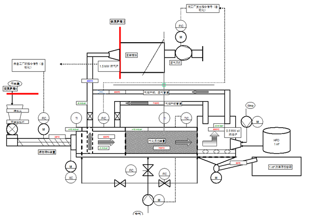
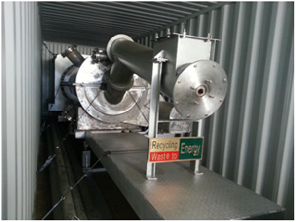
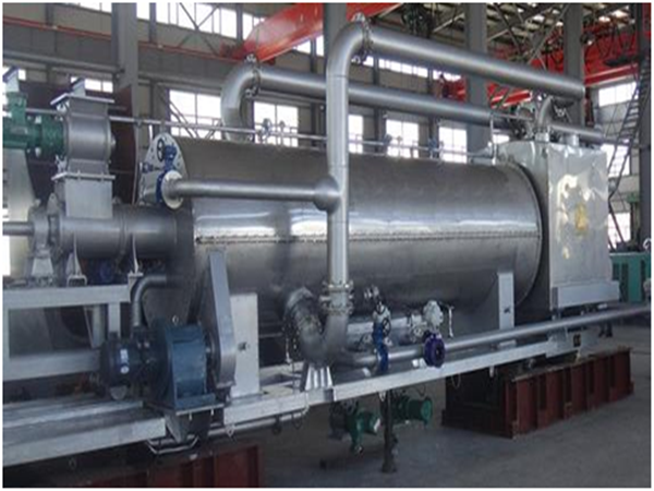
Municipal solid waste gasification power generation device is mainly composed of five parts: material crushing feeding mechanism, waste gasification device, gas purification device, gas generating unit, control device, and auxiliary facilities such as wastewater treatment system, tail gas treatment system and tail slag treatment system.
Solid waste gasification process flow chart
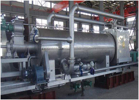
Waste gasification refers to the gasification and pyrolysis of waste gasification raw materials after crushing, drying and processing, which are fed into the gasifier under the condition of less oxygen. That is to say, under certain thermodynamic conditions, organic matter in waste is pyrolyzed, oxidized, reduced and reformed. Tar associated with pyrolysis is further pyrolyzed into small molecular hydrocarbons under the action of catalysts to obtain hydrocarbons containing CO, H2 and hydrogen. The process of obtaining product gas by purifying combustible gases such as CH4.
Solid waste gasification technical feature
Rapid disposal
It takes only 3 minutes for domestic waste to enter the pyrolysis gasifier to generate electricity.
Utilization of resources
After pyrolysis and gasification of municipal solid waste, the combustible gas generated can drive the gas turbine to generate electricity. Solid waste can be made into building materials.
Environmental protection
The whole process of treatment is closed to achieve cleaner production.There is no liquid and solid emissions, and the combustion exhaust purified to meet the standard emissions.
Easy transportation and installation
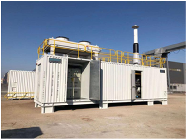
Skid-mounted mobile design, flexible layout.It Can be placed in the source of garbage to achieve the requirements on-site treatment .
Harmless treatment
Waste is treated by pyrolysis and gasification ,it can kill all kinds of harmful bacteria and remove odor 100%.The pyrolysis and gasification process is in an anaerobic reduction environment, which effectively inhibits the production of dioxin, hydrogen sulfide and other harmful gases, and achieves the standard exhaust emission.
High degree of automation
The system uses PLC control, interlocking, automatic alarm in case of failure; automatic detection of linkage feeding, gasification, slag discharge, gas emissions; the operation of system is easy to understand, one person on duty, safe and reliable.
Technical comparison
Comparison of advantages between fixed bed gasification technology and rotary distillation gasification technology
| Current status of waste gasification technology | Main Problems of Gasification Technology in Fixed Bed | Advantages of Rotary Dry Distillation Gasification Technical |
| Fixed bed gasification belongs to fluidized bed technology of vertical furnace. It is easy to produce coking and caustic corrosion in practical application. | Rotary retorting gasification technology has the advantages of uniform heating of fuel, non-coking, precise automatic control of pyrolysis condition parameters (time/temperature), reliable operation of the system and high gasification efficiency. | |
| Carbon content of slag and fly ash in gasification process is high and gasification efficiency is low. | ||
| The contentof tar in gas is high, which affects the stability of power generation equipment and it is easy to produce coke-containing wastewater | Adoppting advanced technology of gas purfication and coke removal .Gas meets the requiement of gas power generatio system,and cocke-containing wastewater is discharged zero | |
|
The effect of Waste heat utilization is not good, resulting in the overall efficiency of the system is low |
The waste heat of system can be used in cascade by circulating cooling system and waste heat recovery equipment, and the energy efficiency of system is 75% |
Parameter Table of System Capability
The solid waste gasification runs for 8000 hours a year. Gasification equipment and power generation equipment are installed in 40GP containers respectively. Gas purification treatment devices are installed on the top of the containers. It is convenient to transport, occupies less land and has strong adaptability, and is not affected by urban planning.
| Distributed Domestic Waste Energy Utilization | |||
| Capacity/Day | 50~60Ton | 60~80 Ton | 80~100 Ton |
| System configuration(Generation power/h) | 500kW | 800kW | 1000kW |
800kW System Capability Parameter Table
| No. | Item | Unit | Value of number | Note |
| 1 | Fuel consumption | tons/year | 20,000 | |
| 2 | Gas output | Nm3/Year | 1,760,000 | Calorific value of gas:1100~1300kcal/Nm3 |
| 3 | Annual capacity | kWh/Year | 6,400,000 | When all gas is used for power generation |
| 4 | Steam production | Ton/Year | 2560 | Combined heat and power generation |
Gas quality control
The highly clean gas generated by solid waste gasification meets the use requirements of gas-fired power generation equipment and ensures the stable and reliable operation of the system.
| Gas quality | Internal combustion engine requirements | |
| Impurit granularity | ≤5μm | ≤5μm |
| moisture content | ≤10mg/Nm3 | ≤40mg/Nm3 |
| Impurity content | ≤10mg/Nm3 | ≤30mg/Nm3 |
| Gas temperature | ≤40℃ | ≤40℃ |
| Tar content | ≤10mg/Nm3 | ≤50mg/Nm3 |
| Calorific value of gas | ≥4.2MJ/Nm3 | ≥4MJ/Nm3 |
Exhaust emission
The exhaust pollutant content of the system is far below the international and domestic standards. Contrast with the strictest Beijing standards in China.
Contrastive Basis: 《Beijing Boiler Air Pollutant Emission Standard 》DB11/139-2015
| Contaminant Content of System Exhaust Gas | Beijing Standard |
| NOx≤20mg/Nm3 | NOx≤30mg/Nm3 |
| SO2≤5mg/Nm3 | SO2≤10mg/Nm3 |
| particulate matter≤5mg/m3 | particulate matter≤5mg/m3 |
| Dioxin | Not produce |
